| FOM 5.4 |
Fleet Operations Manual FOM Vessel Mooring Procedures |
Doc No.: FOM 5.4
Revision: 01 Date: 15 Oct 2024 Issued by: DPA Approved by: MD |
1 APPLICATION
This document applies to the Master, Deck Officer of the Watch (OOW), other Deck Officers and crew and Chief Engineer of all fully managed vessels.
2 PURPOSE
The purpose of this document is to specify requirements and guidelines for the safe and efficient mooring of vessels and rope maintenance. Refer to FOM 5.5 Wire Rope Integrity Management Plan for detailed instructions on wire rope management.
In addition to the generic information provided in this section, each vessel is required to maintain the following ship specific documents:
1. Mooring System Management Plan (MSMP)
2. Line Management plan (LMP)
3. MR02--Mooring equipment and wire-rope tails inspection
3 RESPONSIBILITIES
3.1 Master
- Coordinates all mooring operations.
- Training of the officers to conduct inspection of ropes, wires, and tails, including retirement criteria, and take every opportunity to train members of the crew in mooring and unmooring operations.
- Maintains certification of mooring equipment in coordination with the Chief Engineer.
3.2 Chief Officer
- Inspection of mooring ropes.
- Recording in MR02 as per type of vessels.
Note:
Chief Officer is the competent person to carry out inspection & maintenance of mooring equipment and fittings under the supervision of Master / Chief Engineer.
3.3 Deck OOW
- Ensure moorings are properly secured and tended to for:
- Change of tide.
- Prevailing weather conditions.
- Change of free board.
Deck Officers
- Follow directions from Master during mooring operations and ensure mooring ropes are properly tended to.
- Familiar with retirement criteria of mooring ropes, wires and tails.
Chief Engineer
- Take precautions to ensure mooring equipment is in order.
- Take precautions to ensure mooring equipment is protected against freezing.
4 GENERAL
- Pass adequate mooring lines when alongside, so that vessel remains safely moored at all times.
- Pass additional mooring lines when experiencing:
- Strong tidal current.
- Strong wind.
- Heavy passing traffic in a narrow channel or a river.
- Tend to moorings during the entire vessel's stay at the berth.
- Before starting an operation make sure that all the communication links between the bridge and the officers in charge are tested and working.
- The Master must discuss and agree the proposed mooring plan with the Berthing Pilot and communicate it to the officers in charge of the mooring stations, before mooring begins, where possible include the OOW in the master/pilot exchange discussion.
- The discussion between Master and Pilot must cover the following details:
- the number, characteristics and positioning of tugs, including their bollard pull and the SWL of bitts to be used; use of the vessel’s lines or the tug’s lines for connection;
- the number and sequence of vessel mooring lines;
- the number and sequence of shore mooring lines;
- how to use mooring boats, if any;
- local traffic movements;
- local weather conditions;
- local tide and current conditions; and
- minimum water depth and under-keel clearances (UKCs).
- Where the bollard pull of the attending tugs exceeds the SWL of the bitts to be used, the Master must agree the maximum percentage of bollard pull to be used by the tugs.
- The Officer in Charge must make sure that everyone involved in mooring operation is wearing the correct personal protective equipment (PPE), as detailed in the PPE matrix.
- When mooring operations are completed, the officers in charge must make sure that:
- winch brakes are applied to the correct torque setting.
- number of turns on winch split drums are as per OCIMF Mooring equipment guidelines.
- all winches are out of gear.
- clutch safety pins are in position; and
- winch power is off except on vessels where this is left on for other uses such as on FRAMO pumping system on tanker.
Each mooring fitting including bitts, bollards, chocks, pedestal rollers, closed chocks, universal roller leads and chain stopper to be marked with its safe working load (SWL). Bow stopper should also be marked with its serial number so that certificates can be easily cross referenced.
5 SAFE HANDLING OF MOORINGS
General
5.1.1 Carry out safe mooring operations and take actions to mitigate the associated hazards.
- Vessel shall prepare a Risk Assessment (RA) for each mooring operation. If an existing RA is available for the same port/berth mooring operations, the team shall review the previous RA. In the event of any new hazards or control measures are identified, the vessel shall prepare a new RA.
- Whenever vessel calls a newly built port / berth for which scanty / unreliable information is available in charts and other publications, and which has not been visited by any other company managed ship, the master shall ask the office for guidance and shall forward a copy of RA to the respective marine superintendent for review.
- Information obtained from Pilot as mentioned under section 4 above shall be duly passed on to the officer/person in charge of the mooring party.
- The officer/person in charge of the mooring station shall give a ‘BE SAFE’ briefing to the mooring team just prior commencement of every mooring operation.
- The ‘BE SAFE’ briefing includes ship specific instructions plus the following:
| BE SAFE | |
|---|---|
| Bight | Do not stand inside bights or eyes of the mooring ropes/wires. |
| Evaluate | The condition of mooring equipment prior mooring operations. As a guideline, the equipment to check and evaluate are winches, stoppers, mooring lines, messenger ropes, heaving lines, Mandal shackles etc. (this job shall be undertaken by the mooring team and eventually re-confirmed by the officer). |
| Snapback | Snap back is common for all lines. Even long wire lines under tension can stretch enough to snap back with considerable energy. Synthetic lines are more elastic and thus danger of snap back is more severe. |
| Alertness | Attention to the mooring officer’s/personnel instructions. Do not under-take any actions without clear instructions or orders from the Mooring officer/person. Do not stand in line of tension of mooring wires, ropes, heaving lines, messenger ropes and tug’s line. (Here vigilance of all is very important. As an individual, a person may not be able to keep track in all directions and a buddy system shall be practiced). |
| Fairlead | Appropriate leads shall be determined for mooring lines. Do not blindly work the winch if the winch operator is unable to have an overview unless another person guides him. |
| Explain | Mooring arrangement to deploy and the disposition of tugs and her lines. (this shall be elaborated by the officer in charge for the benefit of the mooring team), also include hazardous mooring zones, protective locations, optimal viewing and sight lines for the mooring officer/person. |
- When ‘BE SAFE’ is completed, it shall be reported to the Bridge and logged in bell book.
- ‘BE SAFE’ poster to be placed at forward and aft mooring station for easy ref. of the mooring team.
Layout
Laying of mooring on winches
When winches are fitted with split drums then adjustment of layers on the tension drum should only be undertaken once all lines are fast.
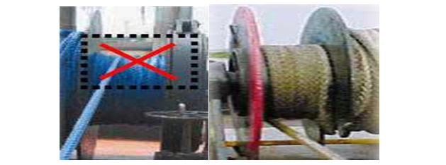
Left: Line installed incorrectly on working (tension) side of winch drum! On working side of winch. Split-drum winches should not have more than one layer of mooring line on the tensions section of the drum because it can reduce the brake holding capacity of the mooring winch. Working part of line should come off end of wraps as shown to right, not from the middle.
Right: Line installed correctly on working side of winch drum. Single layer of wraps on working side of drum. Working part of line comes off one side of wraps as shown.
Usage of Fibre Ropes
Mooring lines of the same size, type and material should be used for all leads so that the strain property (elasticity) is similar, and an equal share of the mooring forces are taken by each mooring rope. Mooring lines should also be arranged so that all lines in the same service are about the same length between the ship and the shore bollard.
Note:
The mooring arrangement in use for the port and its effectiveness should be reviewed. Breast lines provide the bulk of transverse restraint, back springs the longitudinal. Headlines and stern lines contribute much less to the mooring strength than is commonly supposed.
It is essential with Atlas and Karat ropes, as with wire, that the first layer of turns on the winch reel are tight and fully fill the bottom layer. Any slackness or gaps will lead to a lessening of the adhesion required to hold up to full brake power when down to the bottom layer. At least one complete layer is to be retained on the reel at all times and all personnel involved in mooring operations are to be advised of this requirement.
After making fast, mooring winch drum whose lines are under tension should be left on brakes, out of gear to avoid damage to winch machinery.
Soft Ropes (Non-winch mounted)
Polypropylene rope has approximately the same elasticity as polyester rope but is significantly weaker than either polyester or nylon. The use of 100% polypropylene ropes for moorings is not permitted. Modern polypropylene mixture ropes contain a proportion of synthetic fibres such as polyester and they have superior qualities to the traditional polypropylene rope. Soft ropes should be stored in a dry and well-ventilated area, off the deck and away from chemicals or greases. If kept on deck for an extended period, soft ropes should be covered in order to prevent ultraviolet degradation.
Soft ropes should be of flexible construction and material such as 8 strand polyester/polyprop mix and should be buoyant. (Specific gravity < 1.0).
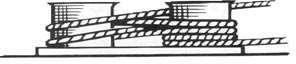
All vessels shall carry number of soft ropes as per trading pattern.
The recommended method of turning a rope up on bitts is to take two full turns around the leading post before ‘figure-of-eighting’. The reason for this is to reduce the tendency to pull the two posts together, whilst maintaining sufficient friction.
Handling and operational risks
Typical operational risks are:
- Risks from manual handling when passing two or more lines together.
- Use of weighted monkey’s fists.
- Failure to have anchors home and housed.
- Rope being paid out from winch drums getting trapped and heaved back in, instead of paying out.
- Lowering too much line too quickly into the water.
- Passing heavy mooring lines ashore, while the vessel is still moving.
- Heaving or slackening mooring lines, without receiving instructions from bridge.
- Heaving or slackening mooring lines, when shore personnel are in the vicinity of hooks/bollards.
- Ensure that all seafarers stand clear of the bight of a rope or wire, which is lying on deck. Seafarer should never stand or move across a rope or wire that is under strain.
- Snapback zones to be discussed during pre-mooring toolbox talk, to ensure that mooring teams are aware of the potential for snapback in the proposed mooring configuration. Painting of conical / typical snap back zones should not be undertaken as areas that are unmarked could present staff with a false sense of security. Please find photos of typical mooring areas wherein appropriate visible signage to be posted is displayed.

- Areas around the mooring area to be coated with non-slip paint.
Risks from poor assessment or watch-keeping
Such risks may arise from:
- While passing the lines, inadequate assessment of tidal situation and effect of bow thruster, tug and propeller wash.
- Mooring line or mooring boat getting trapped between ship and quay, particularly with onshore wind or tide.
- Not monitoring shore personnel on the jetty, when the crew mans the stations on the bow or stern.
- Shore or ship personnel working within the snap-back zones on the jetty.
- Shore personnel not clear of mooring lines when heaving up.
- Failure to consider safety of both ship and shore mooring crew safety when:
- Unberthing as the number of lines is reduced and risk of failure increases on remaining lines.
- Springing a ship off the berth.
6 MOORING STATION DUTIES
General
Master must:
- Plan and assign mooring duties.
- Maintain adequate rest hours to meet mooring requirements.
- Verify compliance with minimum training and experience requirements.
Mooring operations
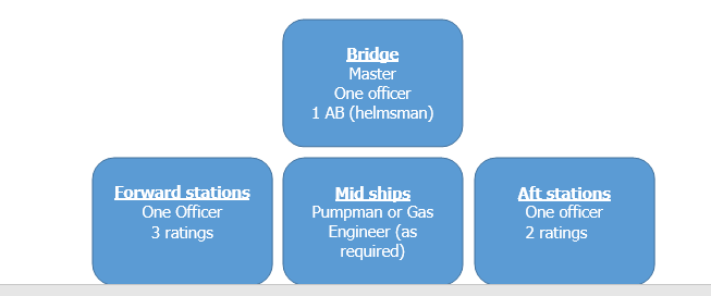
Unmooring operations
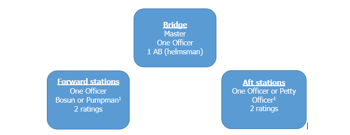
Master must decide on the replacements of a licensed officer on a case-by-case basis taking the following into account:
- Risk assessment is conducted and reviewed
- Master to conduct the safety/PPE briefing for aft station mooring team.
- Petty Officer must be:
- Experienced and has shown good understanding of safe working practices.
- Has carried out 3 unmooring operations under supervision of an officer during this tour of duty.
- Complexity of mooring arrangement to be assessed together with Chief Officer.
7 GUIDELINES FOR MOORING
General guidance
- Ropes and wires shall be correctly reeled on the winch, to ensure correct load application.
- Arrange mooring lines symmetrically around the longitudinal centre of gravity (LCG). This is to ensure optimum load distribution.
- Breast lines are most effective when perpendicular to vessel’s centreline.
- Spring lines are most effective when they run fore and aft. Longer the lead, lesser is the need for tending as the draught/tide changes.
- Smaller the vertical angle, greater is the resistance to a horizontally applied load.
- Mixed moorings are unacceptable because ropes, provide minimal restraint.
- Lines used for the same function must be of similar diameter and length.
- Consider the elasticity of the complete mooring system
- Elasticity is proportional to length (shorter line will take more load).
- Elasticity is inversely proportional to diameter (largest line will take more load).
Vessel above 46 000 DWT (46k DWT)
- Vessels shall be secured alongside with suitable ropes or wires to hold the vessel in place in all conditions.
- The following table lists the minimum mooring requirements by vessel size (OCIMF effective mooring).
- Vessels above 46 k DWT must have moorings at least equivalent to those specified in the table below.
- Where a minimum of 8 mooring lines are required, they must be disposed as breast and spring lines equally distributed fore and aft.
- All mooring lines for vessels over 46 k DWT required by the table below must be fitted on self-stowing mooring winch drums (split type is strongly recommended) and fitted with brakes having a holding capacity in accordance with the table.
- It is strongly preferred that any additional synthetic mooring lines be fitted on similar drums.
| Vessel Size (kDWT) | Number of Mooring Wires | Breaking Strength (Metric Tonnes) | Winch Brake Holding Capacity |
|---|---|---|---|
| 46 – 75 | 8 | 35 | 25 |
| 76 – 100 | 8 10 12 |
70 55 50 |
40 30 30 |
| 101 – 140 | 8 10 12 |
80 65 50 |
45 35 30 |
| 141 – 160 | 8 10 12 |
85 70 55 |
50 40 30 |
Vessels less than 46 000 DWT
- Vessels below 46k DWT must provide an efficient mooring system with sufficient retention capability to securely maintain position while at the terminal.
- The following table can be used as a guide for the smaller vessels calling at terminals.
| Vessel Size kDWT | Number of Lines | Mooring Retention (Metric Tonnes) |
|---|---|---|
| 5 – 15 | 8 | 220 |
| 15.1 – 20 | 10 | 320 |
| 20.1 – 45.9 | 10 | 360 |
| Note: Mooring retention = number of mooring lines multiplied by the breaking strength OR the winch brake holding capacity when fitted to self-stowing mooring drums. | ||
8 MOORING LINES
Wires and ropes construction requirements
8.1.1 Construction of mooring wires
- 6x37 with IWRC
- Galvanized
- Length 220 metres
- Diameter depends on size of the ship
- Mooring wires shall have mechanically spliced eyes.
8.1.2 Construction of mooring rope:
- Blend material of Polyester / Polypropylene
- Braided 8 strand
- Length 220 metres
Glossary and guidance for mooring ropes are given in FOM 5.1 Glossary and guidance for mooring ropes.
Tails and connections
Specification of the mooring tails must be as below:
- Material - Combined fibre and nylon
- Length - 11 meters
- MBL - 125% of MBL of wire rope (In case of nylon tail 135% of MBL of wire rope)
In case of wire ropes, use Mandel or Tonsberg shackle to connect mooring wire and mooring tail. In case of HMPE ropes use COW hitch to connect the mooring line to mooring tail.
Refer to below pictures for correct method of connection.
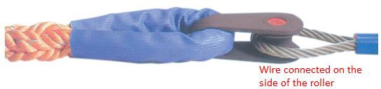
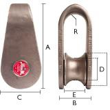
Figure 1: Mandel Shackle (With roller)
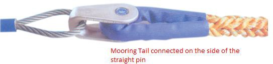
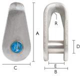
Figure 2: Tonsberg Shackle (with straight pin)
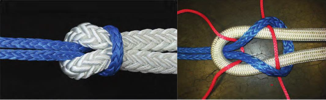
Figure 3: Cow hitch connection - HMSF line to polyester tail
The tail must be served with leather or plastic sheathing. Only one type of connecting shackle is permitted on board a vessel.
Certification and documentation
- Maintain certificates for all mooring ropes, wires, mooring tails and mooring shackles.
- Each certificate must correctly identify the mooring equipment in use and its location.
- Each mooring equipment must be tagged with the corresponding certificate number.
Storage of mooring ropes & tails
- Ultraviolet rays from sunlight can damage synthetic fibres. Ropes should be stored in clean and dry surroundings such as rope locker on departure port.
- Ropes should not be stored near steam pipes or against bulkheads that may reach high temperatures.
- Dirt and grit will adhere to the oil and cause internal abrasion of the rope. If a line becomes oily or greasy, it should be scrubbed with water and mild soap to remove the oil.
9 FIRE WIRES / EMERGENCY TOWING OFF PENNANTS
- Fire wires of emergency towing of pennants must be rigged as agreed upon with the terminal and same is entered in the ship shore safety checklist.
- Following criteria must determine size of fire wire
| DWT | MBL | LENGTH |
|---|---|---|
| Less than 20,000 | 30 tons | 25 m |
| 20 – 100,000 | 55 tons | 45 m |
| 100 – 300,000 | 100 tons | 60 m |
| 300,000+ | 120 tons | 70 m |
Rig the fire wire as per the mooring equipment guidelines. Refer to below drawing.
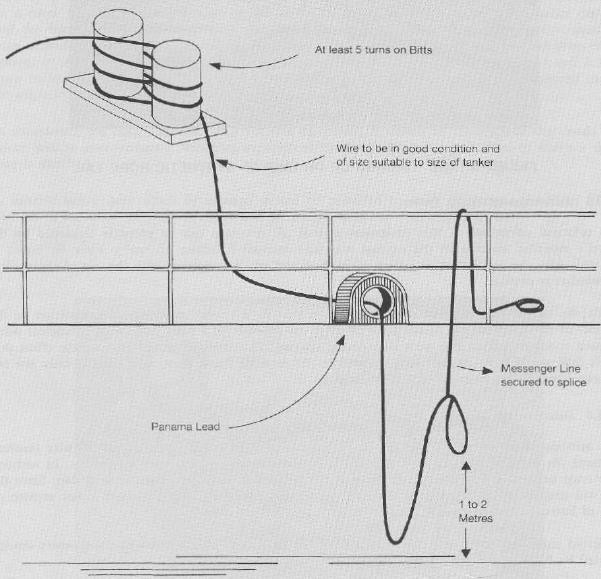
Figure 3: Rigging of fire wire
10 MESSENGER LINES CRITERIA
- Material & construction: Braided polyester or plaited polyester or polyester/propylene mix
- Diameter: 40 mm diameter
- Length: 200 m
- Number of messenger lines: Four (4)
11 WINCH BRAKE TESTING
Brake capacity and testing
Test the winch brake rendering capacity:
- Annually
- After the vessel has experienced excessive strain on the mooring equipment
- Any modification of the mooring winches
- Prior to Ship’s delivery
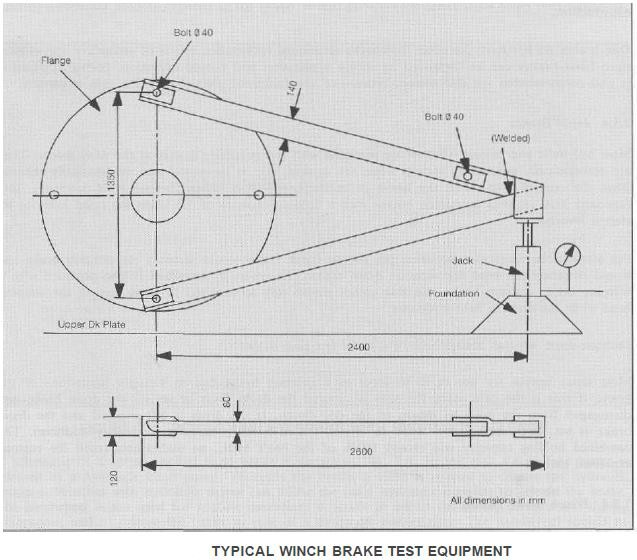
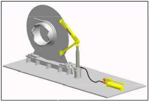
Consider the following:
- After rigging the test kit, tighten the brake to the maximum. The hydraulic jack must be pumped to the desired rendering point
- Slowly release the brake until the brake begins to slip.
- An adequate marking must be made on the brake to mark the rendering point of the brake.
12 SPARE MOORING WIRES AND ROPES
The following may be used as a guideline:
- Two (2) spare mooring wires or ropes (as applicable)
- Four (4) spare mooring tails (if applicable)
- Two (2) spare mooring ropes (which are used as tug ropes)
13 SAFE PRACTICES WHEN OPERATING MOORING WINCHES
13.1 Use of brake
Slacking a mooring line on brakes is dangerous and must not be attempted. If a line has to be slacked down, this shall be conducted with the winch in gear.
13.2 Winch in gear
Leaving a winch in gear and set to heave, must only be considered in emergency situations and shall never be carried out as routine operation.
13.3 Freezing weather precautions
Chief Engineer is responsible for ensuring that steam operated winches are protected against the consequences of freezing, when in operation.
This can be accomplished by:
- Ensure deck lines and steam chests are properly drained, with drain valves left opened.
- Winches are continuously operated at slow speed.