| FOM 5.6 |
Fleet Operations Manual FOM Synthetic Mooring Rope Management Plan |
Doc No.: FOM 5.6
Revision: 01 Date: 15 Oct 2024 Issued by: DPA Approved by: MD |
1. Introduction
The goal of the Synthetic Mooring Rope Management Plan (SMRMP) is to give guidance to the staff on board fully managed vessels and the office staff for ensuring that synthetic mooring ropes, used on various equipment and systems on board, are always maintained in a safe condition.
Note:
Refer to FOM 5.5 Wire Rope Integrity Management Plan for requirements related to wire ropes.
This document covers requirements on how the condition of synthetic ropes should be appropriately controlled at various stages of engagement on board. Requirements are provided on the following aspects in different chapters:
- Chapter 2: Documentation
- Chapter 3: Ordering / Procurement
- Chapter 4: Storage
- Chapter 5: Inspection Frequency
- Chapter 6: Repair, Downgrade and Retire
- Chapter 7: Wear Zone Management
- Chapter 8: Synthetic Ropes: Visual Inspection Criteria
Note:
The implementation of this plan will result in the vessel having a Synthetic Mooring Rope Management System (SMRMS).
2. Documents
2.1 Synthetic Rope Specification and Inspection Record (MR-02 Form)
Use MR-02 Form - mooring equipment and synthetic rope tails inspection record to track the details of the synthetic rope in use or in storage.
The form contains the following information:
- All duties where synthetic ropes are used, with specifications of each synthetic rope.
- Details of PO no., date of procurement, date of renewal (date fitted), supplier, certificate no. etc.
- Observations from scheduled inspections (see Sec.5 Inspection Frequency).
- Damages, repairs, and retirements.
Update MR-02 Form in the following instances:
- When a synthetic rope is brought into service.
- At each inspection throughout the service life of the rope.
- When a rope is discarded and replaced.
Send the updated MR-02 Form to the Vessel Manager and/or MHSSEQ Superintendent every month.
2.2 Synthetic Rope Certificates
File copies of certificates for each synthetic rope (in use or in storage).
2.3 Synthetic Rope Delivery Notes
Copies of the delivery notes of each synthetic rope (in use or in storage) should be filed.
2.4 Design Documentation and Drawings
Vessels must retain the following documents (where available):
- Mooring Arrangement.
- Mooring Foundation drawings.
- Mooring underdeck stiffening.
- Mooring equipment manuals.
- Mooring calculations (where possible).
- Design philosophy including environmental criteria, assumptions, limitations, etc. (where possible).
- Maker’s guidance and instructions for both fixed and loose equipment.
2.5 Mooring System Management Plan (MSMP)
Each vessel, required to comply with OCIMF’s Mooring Equipment Guidelines (latest edition), shall have a MSMP on board with a duplicate copy kept in the office (N Drive).
The documents specified in the preceding sections must be filed in accordance with the MSMP standard outline.
The Company shall provide a standard format and electronic copy for use on board.
Note:
If your vessel does not have a MSMP, please request this from your Vessel Manager and/or MHSSEQ Superintendent.
The MSMP shall contain all ship-specific information related to mooring.
References to the Company Management System (SMS) documents, equipment, and system manuals and other related items shall be made in the MSMP for easy retrieval.
2.6 Events Involving Documentation
2.6.1 Event: New Vessel in Management or SMRMS First Implemented
Relevant documentation:
- SMRMS to be started.
- MR-02 Form to be filled.
- Certificates of each synthetic rope to be filed.
- Delivery notes of each synthetic rope to be filed.
- Synthetic rope thorough examination to be done and records to be maintained in MR-02 Form.
2.6.2 Event: A New Synthetic Rope is Received on Board
Relevant documentation:
- MR-02 Form to be updated.
- Certificate of synthetic rope to be filed.
- Delivery note of synthetic rope to be filed.
2.6.3 Event: Synthetic Rope is Renewed
Relevant documentation:
- MR-02 Form should be filled up with record of first examination, to replace the record of the synthetic rope being discarded.
Note:
Inspection during installation should be carried out.
2.6.4 Event: Thorough Investigation of Synthetic Rope Condition - Periodical or Incidental
Relevant documentation:
- MR-02 Form to be filled/updated.
2.6.5 Event: A New Equipment with Synthetic Rope Installed or Any Modifications Carried Out to Design of Existing Equipment
Relevant documentation:
- MR-02 Form to be updated.
- Certificate of synthetic rope (new/modified application) to be filed.
- Delivery Note of synthetic rope (new/modified application) to be filed.
3. Ordering and Payment
3.1 Requisition
Requisition for a synthetic rope must be raised by the vessel, at least 3 months prior to the intended or expected date of renewal.
All design aspects of the requested synthetics, i.e., material, strength, construction, etc., should conform to specifications in the certificate of the original synthetic rope/maker’s manual. Maximum information from the certificate should be included in the specifications under the requisition. The following should be indicated as a minimum in the specifications:
- Application.
- Equipment details (Make, Model, etc.).
- Material.
- Nominal diameter.
- Length.
- Minimum breaking force.
- Rope construction (No. of strands and no. of fibres/strand).
- Rope core type.
- Direction of lay.
- Type of lay.
- Synthetic rope termination (should be in accordance with makers’ regulatory specifications).
3.2 Procurement
Synthetic ropes should be procured from either of the following sources:
- Directly from rope maker.
- Authorised agents of the rope maker.
- Standard/reliable vendors identified by Purchasing Department of company Group.
Certificate for the synthetic rope should be provided along with the supplied rope.
In case there are any doubts regarding the suitability of the offered or supplied synthetic rope, the rope maker should be consulted for confirming suitability of the available/offered rope before confirmation of order.
3.3 When Receiving On Board
Delivered rope should be visually checked to conform to the specifications in the requisition.
Synthetic rope certificate should be checked to conform to order specifications.
In case of any discrepancies/defects, Vessel Manager and Purchaser should be informed.
Synthetic rope should be stored in a suitable location.
Entry should be made into MR-02 Form.
Copies of certificate and delivery note of the supplied synthetic rope should be filed.
3.4 Factors and Additional Guidance for Procurement
3.4.1 Mooring Information
The LBDF of new, dry mooring lines for which a ship’s mooring system is designed, which meets standard environmental criteria restraint requirement. The ship design MBL is the core parameter against which all the other components of a ship’s mooring system are sized and designed, with defined tolerances.
- Vessel type/size.
- Winch rating, design, and arrangements, including drum storage capacity.
- Mooring arrangement.
- Information on fairleads (type and condition).
- Berth arrangements – exposed/sheltered.
- Trading area/pattern.
- Environmental conditions.
3.4.2 Rope Characteristics
- LBDF (Spliced). The Line Design Break Force (LBDF) is a critical performance criterion when procuring ropes. The specified LBDF should be for spliced ropes, based on break tests undertaken in accordance with ISO 2307. The manufacturer should have type approval for the rope being supplied, issued by an approved third party, such as an IACS member.
- Construction.
- Material.
- Diameter.
- Length.
- Termination (type and required protection).
- Rope protection (jacket, coatings, chafe protection).
- Colour.
- Quantity required (including spares).
3.4.3 Additional Requirements
- Tails if required (type, quantity, length, diameter, and termination).
- Marking - The purchaser should specify the requirements for the rope to be uniquely identified by product labels firmly attached to each end of the rope. The label should include information to link back to the rope’s certificate such as Rope manufacturer, Serial number, Product name, Minimum breaking load.
- Rope Certification - The manufacturer should provide a certificate to accompany each supplied rope demonstrating compliance with the requirements of the purchase order. Certificates may be issued by the manufacturer and/or a third party, such as a classification society. The certificates should identify either a specific line or a batch or run of line that is made into multiple mooring lines. Details on the certificates should include:
- Product name.
- Product type.
- Detailed description - size, length, diameter.
- Detailed description of yarn, including yarn producer and yarn grade or type.
- Details of coatings, jackets, and eyes, as appropriate.
- Weight per unit measure.
- LBDF and test method.
- Identification number.
- Type Certification - A type certificate is a certificate confirming that the rope is manufactured in accordance with the particular design. The certificate may be issued following third party inspection. The Type Certificate will not typically be provided to the purchaser unless specifically requested. Additional test results such as those from cyclic bend or abrasive tests may also be available for specific rope applications.
- Delivery terms and timing.
- Packaging and shipping.
- Training requirements. Especially in case of HMSF ropes. The purchaser should identify any instructional resources required from the rope supplier to support crew training. Training may be in the form of documentation, computer-based resource, or hands-on with a representative from the supplier.
- After-sales support. The purchaser should identify the documentation they require from the supplier. This may include guidance on issues such as:
- Pre-installation preparation of contact surfaces.
- Mooring line installation.
- Safe handling.
- Chafe protection and repair procedures.
- Connection of tails.
- Stopper materials and use.
- End-for-ending.
- Storing.
- Cropping and splicing.
- Mooring log recommended practices.
- In-service inspection procedures and recommended intervals.
- Quality control procedures. Mooring lines should be manufactured and supplied under quality assurance processes that are independently verified, such as those required under ISO 9001 or equivalent.
4. Storage & Preservation Guidelines
- Synthetic rope to be stored in a clean, dry, and well-ventilated place.
- Storage should be away from excessively high temperatures which will reduce a rope’s strength and fatigue resistance.
- Storage should be away from any effects of welding/fabrication activities, chemicals, chemical fumes, steam, or other corrosives, that have potential to cause damage to the rope.
- Where open storage is inevitable, a waterproof covering should be arranged, using a breathable fabric to avoid humidity/condensation problems. The covering should prevent water ingress but should allow an airflow around the rope.
- Periodic outer layer checks should be conducted to establish that no significant deterioration has occurred.
- Stock should be controlled to facilitate the use of the oldest synthetic rope first.
- Details of location, period, preservation, and conditions of storage should be recorded on the synthetic rope’s documentation and should be maintained until the synthetic rope has been retired from service.
5. Inspection Frequency
5.1 General
- The objective is to determine whether or not lines may continue to be used.
- Inspections must be carried out by trained and competent personnel.
- Carry out visual inspections at intervals described below.
- Refer to Ch.8 Visual Inspection Acceptance Criteria to evaluate condition (repair and retire criteria).
- Record and update MR-02 Form after each inspection.
- Report recommendations, repairs, retirements, or uncertainties to the Vessel Manager and/or MHSSEQ Superintendent.
Note:
Chief Officer is the competent person to carry out inspection & maintenance of mooring equipment and fittings under the supervision of Master / Chief Engineer.
Caution:
The frequencies described below are the minimum required frequencies required for all fully managed vessels in the Company. Inspection frequencies may be increased (never decreased) depending on, amongst others, mooring frequency, severity of loading conditions and consistency of line configuration and use.
Vessels shall additionally refer to maker’s recommendations and comply with the stricter frequency.
5.2 Pre-use Inspection (Deployment)
Frequency:
- Every mooring operation.
Who to inspect:
- Trained mooring party members.
Extent of inspection:
- The working length of the line (outboard of the tension side of the winch), i.e., all visible parts of the synthetic rope is to be visually checked to the maximum extent possible.
If damage/deterioration is detected:
- A competent person should examine the synthetic rope.
- Report the damage and update MR-02 Form.
- Assess synthetic rope condition against discard/retire criteria.
- Renew synthetic rope if damaged/deformed beyond acceptable limits.
5.3 Routine Inspection
Frequency:
- 3 months.
Who to inspect:
- Competent person.
Extent of Inspection:
- The full length of line on the in-service section of the line (typically on the tension side of the mooring winch).
- Carry out external and internal inspection where possible (unjacketed lines).
- Rope section which has identified stiffness along its length should be massaged to remove the stiffness and restore elasticity in that section.
- Closely inspect all visible and accessible parts of the rope and, as far as possible, inspection of the inner strands.
- The inspection should include checking for the security of strands in splices.
Note:
Jacketed lines will require a routine inspection as recommended by the line manufacturer.
If deterioration is detected:
- Report the damage and update MR-02 Form.
- Assess synthetic rope condition against discard criteria specified in this chapter below under Sec 6 Repair, Downgrade & Retire.
- Renew synthetic rope if damaged/deformed beyond acceptable limits.
5.4 Detailed (Thorough) Inspection
Frequency:
- 6 months.
Who to inspect:
- Competent person.
Extent of inspection:
- Either the full length of the line, or the full length of the in-service section of the line (typically on the tension side of the mooring winch).
- Carry out external and internal inspection where possible (unjacketed lines).
- Identification of rope by its label or permanent marking.
- Inspection for powdered fibre inside the rope strands.
- Feel along the length of the rope, inspect for:
- Abrasion, Glossy or glazed areas, Inconsistent diameter, Discoloration, Inconsistency in texture and stiffness.
- For jacketed rope, inspection has to be made for:
- Bulging.
- Herniation.
- Difference in rope diameter along its length.
- Damage to jacket.
Note:
Jacketed lines will require a detailed inspection as recommended by the line manufacturer.
5.5 Incidental Inspections
An inspection should be carried out immediately after an overload or any incident which may have caused significant damage to a synthetic rope. The results of the inspection may identify the need for a thorough examination by a competent person.
6. Repair, Downgrade and Retire
6.1 Repair
If the rope shows severe damage only in a few concentrated areas, it may be possible to remove the damaged sections and resplice the rope. After completion of new eye splices or end-to-end splices, pretension or load cycle to set the splice preparación si es posible. For end-for-end splices, assume 100% strength for a short splice and 80% for a long splice.
Caution:
Splicing of a heavily used rope may be impossible, or very difficult (double braided nylon rope can be particularly bad). In such cases, there is often a significant strength loss; consultation with a qualified person may be appropriate. For jacketed ropes where the core is the strength member, it may be possible to repair the jacket. Follow manufacturers’ or other governing guidelines or directions of a qualified person.
6.2 Downgrade
- If a rope is damaged and cannot be repaired, the residual strength of a rope can only be estimated by the inspector. The decision to downgrade a rope must be made very conservatively.
- Destructive strength testing of yarns or of a specimen of the rope can be utilized to estimate residual strength when making the decision to downgrade. Test ropes in accordance with Cordage Institute Standard Test Method CI 1500-(current).
- Using estimates of the reduced breaking strength of a degraded rope, the inspector or user must determine a working load limit (WLL) based on a design factor established by the user.
- The user must make certain that downgraded ropes do not find their way into the original or other applications that require full strength.
- Downgrading may also apply to ropes that have been repaired by splicing as used rope splices may have questionable strength.
6.3 Retire
- Rope must be retired if it is damaged and cannot otherwise be repaired or a use cannot be found for it in a downgraded condition.
- The rope has more than two splices within its length.
- 25% of material is lost through abrasion. Localized reduction or increase in diameter is observed.
- Localized area of stiffness is observed.
- Extensive area of heat fusion is observed.
- Discolouration caused by chemical contamination is observed.
- If rejection factor reaches 100% based on the criteria described in section 8.5.
- Normal ropes: 5 years (for dry bulk vessels) and 7 years (for other vessels).
- HMPE ropes: 5 years (for dry bulk vessels) and 10 years (for other vessels).
Note:
HMPE ropes can be extended up to 15 years (for vessels other than dry bulk vessels) provided these ropes are inspected after 10 years of usage by a rope manufacturer’s recommended expert and are certified to be in good condition.
6.4 End to End Change
Dry-bulk Vessels
- All ropes (normal and HMPE) should be turned end to end every 2.5 years to distribute wear.
All Vessels Other Than Dry-bulk Fleet
- Normal Ropes other than HMPE ropes mounted on winch should be turned end-to-end after about 3.5 years (+/-6 months) to distribute wear, unless inspection dictates a shorter schedule.
- HMPE Ropes mounted on winch should be turned end to end as follows:
- 5.0 years from the date of installation.
- 2.5 years from the date of maker 10th year inspection, if ropes are extended to 15 years usage.
7. Wear Zone Management
All types of mooring experience localized fatigue and damage caused by common line routing and deployment processes. E.g., damage from loading cycles while routed around pedestal rollers, local abrasion from contact with fairleads and rollers while under tension. Location and extent of this damage may vary due to several factors including:
- Variability in trading pattern.
- Terminal layout and design.
- Mooring tail length and material.
- Environment condition.
- Laden or ballast ship.
Following picture highlights some sections of rope which are susceptible to wear. Length at which wear can take place varies from port to port depending upon the length of mooring line used to the dolphin ashore.
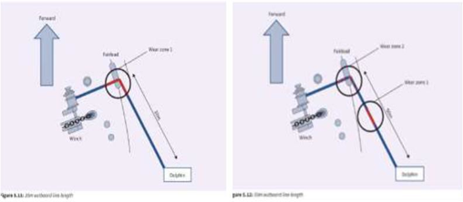
To manage wear zone effectively, the following should be considered:
- Each ship should check the layout of the mooring system and identify sections of each rope which are prone to operational damage due to contact with pedestal rollers, bits, or fairleads under tension.
- Consider purchasing rope of suitable length to allow sufficient residual length after cropping and re-splicing of damaged sections.
- Provide chafe guards to all ropes to prevent abrasion damage from chocks/fairleads, etc.
- Never drag ropes over sharp edges, or over surfaces where abrading particles can penetrate between strands and yarns.
- Avoid unnecessary chafing at fairleads, over bulwarks, wharf rails, etc. All metal parts should be smooth and chaffing points protected by leather, plastic, or canvas parcelling, or by worming with small-sized ropes. Examples of chafe protection are shown below:
- Winch drums must be smooth and free from rust or paint. Fairleads should be in a similar condition and, if of the roller type, should be free running and the bearings well-greased.
- Avoid contamination by chemicals or fumes as this can damage the ropes. If contamination is suspected, wash the ropes in cold running water, e.g., by hosing.
- Avoid exposure to all forms of heat. Ropes should not be left exposed to sunlight whilst at sea; they should either be covered or stored below deck.
- Avoid build-up of excessive turn in ropes. If this condition has occurred, loops will form, and, if loaded, strand distortion and loss of strength will result. Work excessive twist over the end of the rope before straining.
- Never couple a right-hand laid rope to a left-hand rope no matter what materials are used. If the rope is delivered on a reel, mount the reel on trestles and unreel with the rope coming from underneath the reel.
- If the rope is delivered in a coil form, try to keep it off the floor as dirt and damp can damage the rope. Always draw the rope from the middle of the coil bringing it out anti-clockwise.
- Ropes should not be surged on winch drum ends or slacked away by rendering; ropes should be walked back so far as possible.
- Sharp angles in the lead of the rope are to be avoided and it must be remembered that these may exist when the mooring rope runs along the hull between the fairlead and the mooring bollard on the wharf.
- Ropes should not be led such that they cross other ropes, which could lead to wear during the port stay.
- Cover all the mooring ropes with Canvas or Tarpaulin after use or place them inside stores to prevent UV exposure on long voyages (> 3 days).
- Loose mooring ropes should be placed on wooden pallets for added protection.
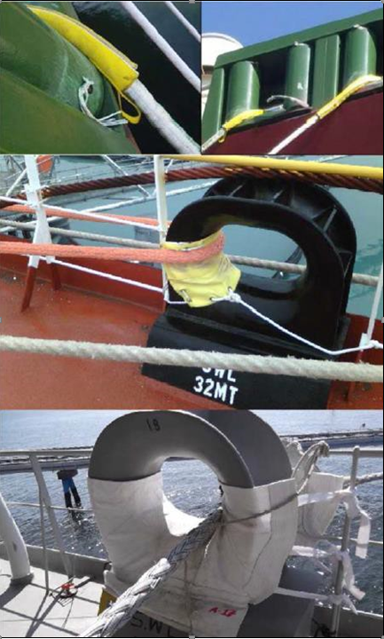
Mooring Tails
- Provide chafe guards to all ropes to prevent abrasion damage from chocks/fairleads, etc.
- While storing on drums, avoid contact of the rope tails with the grease on mooring wires by placing tarpaulin over the wires or putting the tails on the split drum.
8. Visual Inspection Acceptance Criteria
8.1 General
The visual inspection of the synthetic mooring ropes should be performed in accordance with the guidance provided in this chapter.
8.2 Type of Rope Materials
There are two types of Mooring Ropes used within the fleet, High Modulus Synthetic Fibre (HMSF) Ropes and Conventional Synthetic Fibre Mooring Ropes.
8.2.1 High Modulus Synthetic Fibre (HMSF) Ropes
- High Modulus Polyethylene (HMPE) - High strength to weight ratio and low stretch characteristics but limited resistance to high temperatures. The fibres have good abrasion resistance and tension-tension fatigue life. Mooring lines constructed from 100% HMPE fibres float.
- Aramid fibres - High strength and low stretch. It does not creep significantly and does not melt, but chars at high temperatures. Aramid ropes do not float.
- Liquid Crystal Polymer fibres - High strength and low stretch and good resistance to creep and tension-tension fatigue. The fibre has a temperature resistance between that of HMPE and Aramid.
8.2.2 Conventional Synthetic Fibre Mooring Ropes
- Polyester - It has high strength, both wet and dry. It has good resistance against external abrasion and does not lose strength rapidly due to cyclic loading.
- Polyamide (commonly referred to as ‘Nylon’) - Loses strength when wet. This factor can be anything up to 15%. It should be noted that polyamide ropes do not recover break strength when going from a wet to dry condition.
- Polypropylene - Approximately the same elasticity as polyester rope. Polypropylene has limited temperature resistance and has poor cyclic loading characteristics. Prolonged exposure to the sun’s ultraviolet rays can cause polypropylene fibres to disintegrate.
Combination of Materials
- Polyamide mono and multifilament fibre mixtures - These lines are very compact, have good abrasion resistance, and are generally designed for use as winch‐mounted lines.
- Polyester/Polyolefin dual fibres - Polyester fibres covering a polyolefin core.
- Polypropylene/Polyester melt mix - Melt mixture of polyester, polypropylene during fibre extrusion.
- Mixed Polyolefin Ropes - Bi‐component fibres made of a blend during extrusion of polypropylene and polyethylene.
8.3 Type of Rope Construction
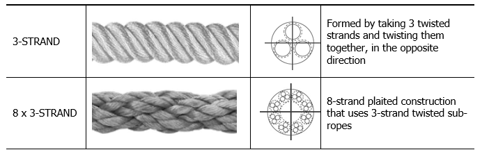
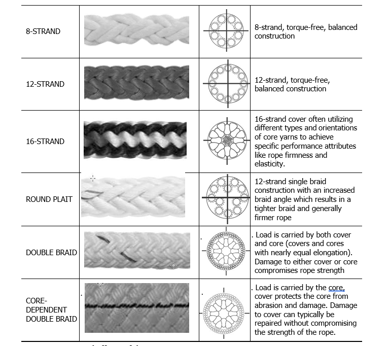
8.4 Types and Effects of Damage
Knowing the causes and appearance of damage is essential to a good rope inspection and essential in determining retirement criteria. This section describes the most common causes of rope damage and describes the effects.
Smaller ropes, due to their reduced bulk, suffer a proportionately larger loss of strength than larger ropes due to cuts, abrasion, and environmental exposure. Extra attention is recommended when inspecting small diameter ropes.
8.4.1 Excessive Tension / Shock Loading
Overloading or shock loading a rope above a reasonable working load limit can cause significant loss of strength and/or durability. However, the damage may not be detectable by visual inspection. Repeated overloading will result in similar damage as that caused by cyclic fatigue as described in the next section.
8.4.2 Cyclic Tension Wear
Ropes that are cycled for long periods of time within a normal working load range will gradually lose strength. See below figure where long-term loading and unloading has caused a breakdown of yarns in the outer braid of a double braided rope (lower picture). This rope was also extremely hard due to internal compaction of broken fibres. Compare to the upper picture of relatively new rope which was soft and flexible.
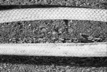
Fibre Abrasion – Cyclic Tension
Undamaged - Upper Photo
Braided ropes develop many broken filaments at the crossover points of strands in the braid due to fibre-on-fibre abrasion. Below figure shows extreme examples of braided ropes that exhibit excessive damage from frequent loading and unloading.
(Extreme Wear)
For braided ropes, broken filaments within the rope can also mat, entangle, and/or leave a powdery residue. See below figure for exposing the inside of the structure.
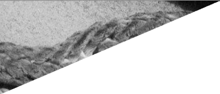
Inter-Strand Abrasion
(Exposed internal area reveals wear at strand internal contact points)
For 3 strands twisted and 8-strand plaited ropes, most of the wear will occur on the inside of the rope where the strands rub on each other.
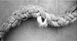
Matted Internal Yarns
(Exposed strands reveal internal matting)
Wirelay ropes usually have a non-load bearing jacket and must be examined under the jacket. Broken filaments, powdery residue, or fusion may be observed if the interior can be examined.
8.4.3 External Abrasion
Most external abrasion is localized. Gouges and strips along one side of the rope are common; these display cut fibres and are often accompanied by fusion.
Uniform Surface Abrasion
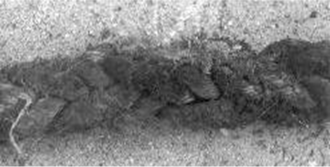
Extensive External Abrasion
Localized External Abrasion
The surface of the rope may be melted and appear black due to sliding while bent over surfaces when under high tension. See below figure.
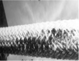
Burn and Melting from External Abrasion
Jacketed ropes require inspection of the outer sheath. The load-bearing core should not be exposed. Loose strands that may snag could be a consideration in some cases.
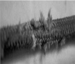
Localized Jacket Wear
8.4.4 Cutting
It is obvious during visual inspection to see where fibres have been cut sufficiently to degrade a rope. Damage assessment includes an evaluation of the amount of affected fibre, and location and orientation of the cut.
For jacketed ropes where the jacket is non-load bearing, a cut that does not damage the core will probably not affect the strength. See below figure.
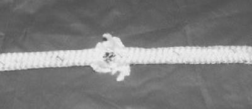
Cut in Jacket Exposing Core
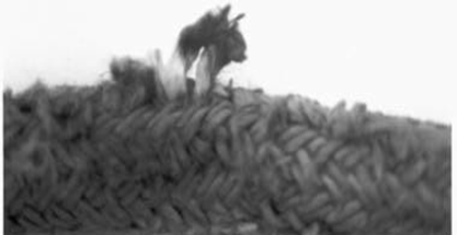
8.4.5 Pulled Strands and Yarns
Strands and rope yarns can be snagged and pulled out of the rope structure.
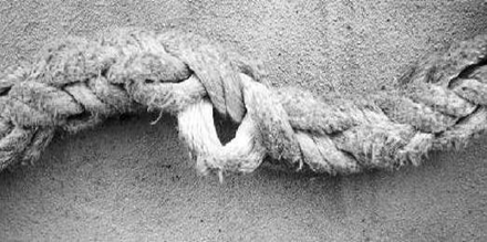
Pulled Strand in 8 Strand Rope
Pulled Strand in Worn Double Braid
(Note color difference due to external dirt)
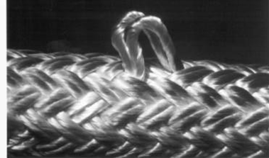
Pulled Strand in New Double Braid
8.4.6 Flex Fatigue – Pulleys, Rollers, Chocks, Fairleads, Blocks
Constant bending of any type of rope causes internal and external fibre abrasion. This is frequently caused by running on pulleys.
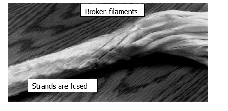
External & Internal Damage – Running Over Pulley
8.4.7 Spliced Eyes and Other Terminations
Check for a properly made eye and end-for-end splices; splices should always be based on manufacturer’s instructions. A long splice for end-for-end is about 80% efficient; consider this when establishing a SWL. A properly made 3-strand eye splice is shown below.
Properly Made 3-Strand Eye Splice
Damage is common at splices. See below figures.
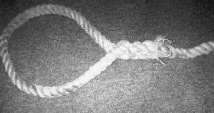
3-Strand Splice of Poor Quality
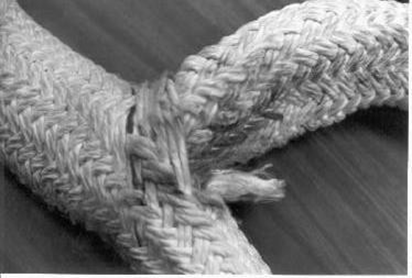
Wear in Double Braid Eye Splice
Tearing at Leg Junction of Eye Splice
Lock stitching should be used with bury splices on single braided rope. Check to see if they are present. They are often found on double braided ropes. In both cases, they should not be broken.
Parallel fibre ropes and some parallel strand ropes require a continuous whipping function. Damage that allows the whipping to come loose can be dangerous.
8.4.8 Creep (Cold Flow)
Creep is the tendency of a solid material to slowly move or deform permanently under the influence of load. Creep always increases with temperature and is more severe in materials that are subjected to heat for long periods. The rate of deformation is a function of the material properties, exposure time, exposure temperature, and the applied load. Depending on the magnitude of the applied load and its duration, the deformation may become so large that a component can no longer perform its function, resulting in failure.
There are two key properties of creep, namely creep strain and creep rupture. Creep strain is the non-recoverable increase in length and creep rupture is the failure that occurs after a period of time with an applied load. Rope creep is of particular concern when evaluating ropes that operate under high loads and/or high temperature.
8.4.9 Axial Compression and Kink Bands
Ropes that have a braided or extruded jacket over an inner, load-bearing core are subject to axial compression, as manifested by kink bands.
Kink bands can also appear in splices of very high strength, high modulus ropes.
Often seen on winch drums, compression is caused by fibre molding itself to the contact surface while under a radial load. Compression can be identified by a visible sheen and stiffness that can be reduced by flexing the rope. Compression is not a permanent characteristic and should not be confused with melted or glazed fibres.
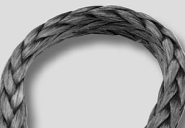
12 – Strand Rope with Axial Compression
8.4.10 Hockle, Twist, Kink or Corkscrew
If a loop is introduced into a 3-strand rope (or other multistrand laid rope), it will tend to hockle when tension is applied. Once set, hockles cannot be turned back to restore the rope structure and this indicates severe damage.
Hockle
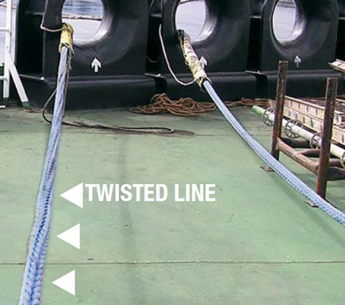
Some ropes will display a corkscrew appearance and must not be used unless restored to normal appearance. See below figure.
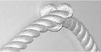
Corkscrew Due to Twist
Braided and plaited ropes should display little or no twist, and those that do must not be used unless restored to normal appearance. See below figure.
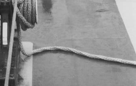

8.4.11 Sunlight Degradation
Ultra-violet (UV) radiation from direct sunlight will cause brittle and weak outer rope yarns. UV degradation is difficult to inspect visually. Discoloration and brittleness in the filaments may be observed in some cases.
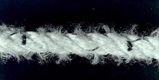
UV (Sunlight) Degradation of Polypropylene Rope
8.4.12 Chemical and Heat Degradation
Synthetic fibre materials generally resist chemical attack and heat exposure in normal circumstances but can be weakened in certain situations. Visual inspection may reveal discoloration/brittleness of the fibres, melting/bonding of fibres, hardening or stickiness may be observed.
Nylon ropes, when wet, can be seriously degraded by long-term contamination with rust. This can be detected by the reddish or brown colour.
Fibre ropes stored at even moderately high temperatures for long periods of time can be degraded without any visual indication of damage.
8.4.13 Dirt and Grit
Dirt and grit cause internal fibre abrasion in ropes that are in regular use. Most ropes can be forced open for internal inspection.
Sea water that has dried and has left a salt deposit can be damaging due to internal abrasion if the rope is used in the dry condition.
8.5 Inspection and Retirement of Ropes
Rejection Factor of Mooring Ropes
A frequent and thorough inspection program is required to ensure that a rope/wire is removed from service before its strength is substantially reduced. The inspection procedure is based on a system of points (rejection factors - RF) which are allocated after each inspection of the rope.
There are areas of inspection, which are described below along with guidance on what to look for and, if applicable, when the rope should be rejected (RF = 100%). A rejection factor percentage is assigned for each of these inspection areas and it is the cumulative total sum of the rejection factors awarded that should be considered when determining the action to be taken.
| Rejection Factor | Action |
|---|---|
| 0%, 20%, 40%, or 60% | Continue with existing time period (bi-annually) for thorough examination. |
| 80% | Plan for renewal of rope at next suitable opportunity. Reduce time period for thorough examination from bi-annually to quarterly. |
| 100% | Discard / Renew rope immediately. |
Caution: If any rope has rejection factor of 60% and above, new replacement rope to be ordered immediately.
Aid for Assessing Synthetic Rope Rejection Factor
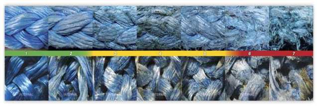
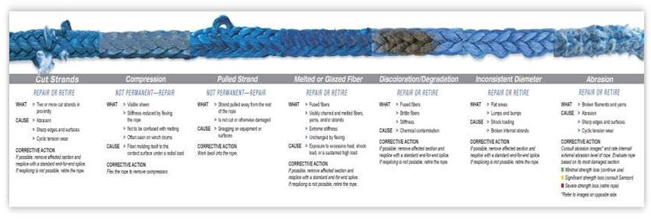
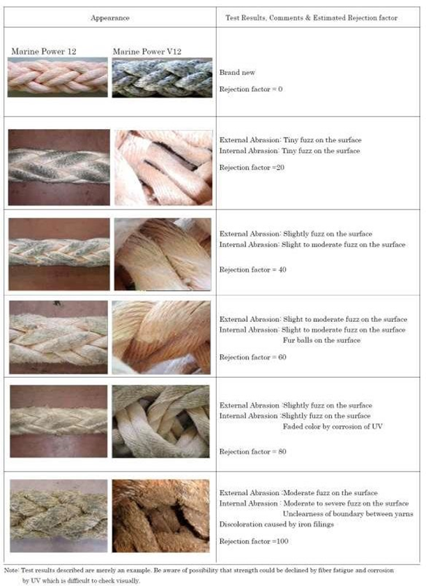
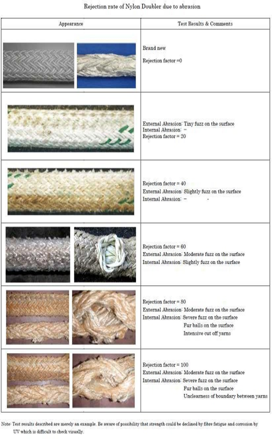
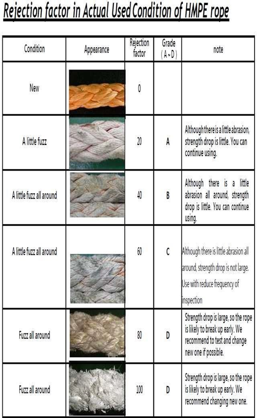
Following Contribute to 100% Rejection Factor
- Broken Strands
- > 25% of fibres cut, fused, or badly abraded in a single cross section.
- Rope not fit for use and should be replaced immediately or consider crop & splice.
- Splices
- > 2 joining splices on full length of rope. RF = 25% for each splice.
- Length
- < 80% length of initial rope length (176m of a 220m rope). If required by any terminal, minimum length required can be increased. (e.g., ‘Port Hedland’ requires minimum length to be 200m).
- Surface Damage
- External Abrasion damage (Area 50% or more).
- Heavy surface fuzz-progressive.
- Oil and Grease (Wash in mild detergent).
- Abrasion on inside radius of eye, with bulk of surface yarns or strands reduced by 50% or more.
- Hockles that cannot be removed.
- Exposure to chemicals.
- Thermal Damage
- Melting or fusing affecting 10% or more of rope yarns in a cross section.
- The rope shows hard, melted, flattened areas.
- Exposure to excess temperature as specified for type of fibre.
- Internal Degradation (10% of rope yarn)
- Powdering between adjacent strand contact surfaces.
- For Braided Jacket Ropes
- Cover jacket is damaged. Determine core coverage and assess criticality of coverage for particular application (core is undamaged).
- Core damage – pulled, cut, abraded, powdered, or melted strands.
- Herniation - core pokes through cover (sheath) which cannot be massaged back into original structure.
- Inconsistent Diameter (For HMPE Rope)
- Inconsistent Flexibility (For HMPE Rope)
Note:
A Rope suspected of being shock loaded more than SWL should be condemned