| OTM-7.5 |
Oil Tanker Manual OTM Carriage of cargo in cold climates |
Doc No.: OTM 7.5
Revision: 01 Date: 15 Oct 2024 Issued by: DPA Approved by: MD |
1.CARRIAGE OF CARGO IN VERY COLD CLIMATE
One of the critical aspects of low temperature is the potential of steel going below the point where fracture is ductile, thus exhibiting brittle behaviour. The majority of steel utilized for the construction of cargo tanks is mild steel for which there are no fracture toughness requirements. Criteria are defined to assess fracture toughness at sub-zero temperatures.
Operational measures like slow heating of cargo with ballast water are proposed. Fast heating with heating coils and/or deck heaters can also be employed.
Cold cargoes under consideration might be naphtha, gasoil, gasoline and gas condensate; all having freezing points well below -40 C.
Vessels to enact appropriately low filling/ de-ballasting rates and possibly use the ballast water or heat exchangers on deck to heat up the cargo.
This may be necessary since many receiving ports have a minimum acceptable cargo temperature. Further the large thermal inertia of the cargo and the thermal insulation of modern double hull tankers do not enable significant warming of the cargo during the transit voyage. Heating with ballast water should take place at ballasting rates of about 200 m3 /h on one tank only. Heating is fast in the beginning stages with cargo temperature rising at a rate of the order of about 0.5 C per hour. Heating slows down as the cargo mass increases.
Heating with ballast water needs to be investigated regarding its effect on the cargo heating. Given the direct contact with the sea there is significant energy loss due to heat transfer to the sea. It is recommended to circulate the cargo in parcels. Ballast heating is also safer for heating a cargo with a low flash point. Ballast should be loaded up to the draft level to avoid freezing above the water line. The top surface of ballast water might freeze and thus create an effective insulator. Ballast exchange will promote heat transfer during this operation. Cargo with flash point below 60 degrees Celsius or a boiling point below 140 degrees Celsius should be heated by ballast.
Adjacent ballast tanks may be accepted as a heating source for the cargo tanks provided that the ice accretion on the ballast tank walls does not exceed 10% of the tank width (lateral tanks) or height (bottom tanks), which is to be justified by heat transfer calculations. If the 10% limit is exceeded, the ice layer will act as an insulator. Ideally, ballast tanks must be provided with de-icing arrangements. As far as practicable with respect to the ship safety (stability and structural integrity), the level in the ballast tanks is kept as close as possible to the ship water line. Arrangements are to be made to circulate the liquid cargo in the tanks during cargo heating-up. Temperature sensors and thermometers intended for the cargo are to be suitable for temperatures down to -25 degree Celsius.
Ballast valves must be opened easily. Valves on deck must be thermally insulated because they can become inoperative due to ice formation and clogging. In addition the risk of fracture due to the volumetric expansion of ice is perennially present.
Heat exchangers on deck can also be utilized while the cargo pump is running. Steam in the heat exchangers is introduced at around 130°C. The flow rate of pumping cargo must be computed to avoid freezing of steam, otherwise the heat exchanger will be damaged. Another safety critical aspect when using heating by heat exchangers comes into play if the cargo has low temperature boiling point, presenting the risk of explosion. Alternatively part of the cargo can be warmed at the slop tanks and then mixed with the cold cargo. Cold cargo can cause freezing of the steam in the coil and cause fracture due to the volumetric expansion of ice. Boilers may not have the required capacity for heating the cargo. The heaters are to be kept in permanent operation or drained and isolated after each use so that they may not be rendered inoperative due to ice build-up or thermal oil gelation. Heaters can be also placed at the manifold.
The steam thermal oil pipes supplying the heaters are to be provided with efficient thermal insulation so as to provide the highest heat level at the heater inlet. The condensate lines are to be provided with heat tracing and be suitably insulated. The valves serving the heaters are to be installed with heating and thermal insulation allowing their operation in the worst expected conditions. Means are to be provided to monitor the proper operation of the heaters. In general, heating coils would be preferable over deck heaters. In ships intended to be loaded with liquid cargoes having a cargo temperature below -10°C the following arrangements are to be made:
- Prevention of excessive ice build-up in the ballast tanks located adjacent to the cargo tanks. Ice may be detrimental to the ship structure.
- Prevention of freezing of the heating medium in the cargo heaters and in the piping system.
- Maintenance of the temperature of the heated cargo in all heaters below its boiling point.
- Maintenance of the temperature of the cargo in the tanks below its flash point.
- Oil products are not to be directly heated by steam or thermal oil having a temperature exceeding the boiling point of the product.
Risk assessment is to be performed covering the scenarios of potential overheating of the cargo due to insufficient circulation, cargo pump failure, etc., which could lead to the creation of an explosive atmosphere. Other hazards which need to be mitigated are the freezing of the heating medium due to the low temperature of the cargo and the excessive ice build-up in the ballast tanks.
A critical element is time since terminals cannot wait.
Time involved is critical because of the terminal imposed time limits. Heating with ballast including the assessment of freezing of ballast in a petrochemicals cargo ship needs to be investigated with a transient heat transfer model. Transient analyses introduce the element of time and not just the estimation of the final equilibrium state. It is necessary to have a relatively simple and robust model which will provide quick and accurate results. A simplified 2-D model of the cargo hold and ballast is depicted in Figure 1.
In that model the ballast is loaded up to the draft of the vessel. The quantity of cargo can be found in such a way as to have the desirable heating within acceptable time. The 2-D model shown is a transverse slice of the cargo hold. Given the simplicity of the model, multiple scenarios/combinations can be explored and estimated.
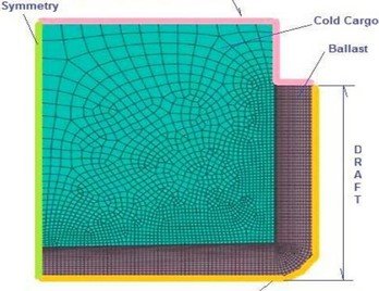
Free convection h = 5 W/Km2. Temperature boundary condition Heat transfer model of cargo-ballast.
The model extends from ship centerline up to the seawater. Only the part of the cargo hold which is actually loaded (95-98% of the height of the cargo tanks) is modelled, and only the part of the ballast tanks which is filled is included (up to max. draft height). Ship steelwork is not included in the model, assuming that the cargo is in direct contact with the water found in the ballast tanks. This assumption is equivalent to assuming infinite conductivity for steel. The ballast water temperature is equal to the sea water temperature on the outer boundary which is normally in contact with the hull.
Free convection with a coefficient equal to h = 5 W/m2K is assumed for both free surfaces in the confined space in the ballast and cargo tanks. The symmetry boundary condition on the centerline is implemented through specification of zero heat flow rate (as if there was insulation along the centerline). The outer surface of the water in the ballast tanks is assumed to have constant temperature equal to the sea temperature. The air temperature in the cargo hold and in the ballast tanks must also be specified.
The heat transferred from ballast to the cargo follows the following energy balance relation:

Where M cargo and M ballast are the masses of cargo and ballast respectively, CPH cargo and Cp seawater are the specific heats of cargo and ballast. T cargo and T ballast are the corresponding temperature changes.
Sea water properties change as a function of state. Sea water freezing is assumed to take place at - 2°C. Above Equation represents the so called “lumped system" approximation which is valid only in case of uniform temperature distribution throughout the body. This is true only when the thermal resistance of the body to heat conduction is zero. Another way to assess the validity of the lumped system approximation is through the calculation of the non-dimensional Biot a number. This number represents the ratio of resistance to conduction within the body to the resistance to convection on the body surface. The smaller the Biot number (below 0.1) the more accurate equation (1) becomes. In our ballast-cargo problem the Biot a number is larger than 0.1, and lumped system cannot be assumed. The temperature within the liquids changes appreciably from point to point as well as with time.
The equation governing the temporal and spatial distribution of temperature, T is the well-known equation (2):
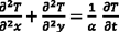
Where a = K/ PCp is the thermal diffusivity, with k, p, Cp the conductivity, density and specific heat respectively. Equation (2) is solved numerically in time at discrete time steps taking into account potential freezing of ballast water.
In general ships which have to carry cold cargoes do not suffer from inferior steel when it comes to susceptibility to brittle fracture. Experience points out more towards operational problems and challenges. Cargo needs to be heated to temperature acceptable to the receiving terminal. The team needs to determine the proper means of heating the cargo, within the time limits allowed and with the means available. Ideally, the solution must be found by a combination of the right equipment, at the right place, in the right time. To this end, numerical computations can be a valuable companion to operational experience.
Note:
- Master is required to advise MTSI in case voyage nomination includes any port where near sub-zero temperatures expected. (This holds good for both ballast and laden voyages)